
Products · Tilting And Turning
HYDRAULIC UPENDING SYSTEMS
Hydraulic Load Upender
Controlled 0–90° Positioning for Coils, Dies and Special Loads
Custom industrial load tipping with double-acting hydraulic cylinders and application-specific L-platform or V-cradle construction.
- Up to 50 t
- Handling capacity
- 0–90°
- Controlled angular positioning
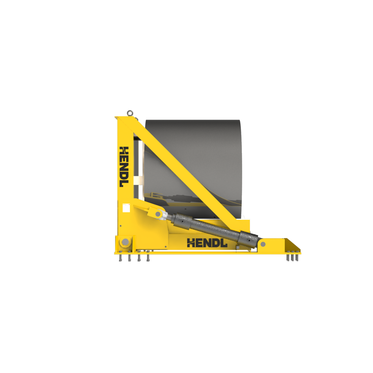
Frame loading
Product introduction
The HENDL Hydraulic Load Upender is engineered for controlled tipping, upending and angular positioning of metal coils, industrial dies, transformers and other special loads. The product family can be configured for capacities up to 50 metric tonnes, using either an L-shaped hinged platform or a V-cradle structure to suit the application. Double-acting hydraulic cylinders powered by an electric hydraulic power unit provide movement within the 0–90° range. Higher capacities and non-standard load geometries are subject to custom engineering.
Standard Capacity And Dimensions
- Capacity
- up to 50 metric tonnes; larger duties by special engineering.
- Movement
- controlled angular positioning within 0–90°.
- Tipping time
- 30–90 seconds, depending on load and project design.
- Structure
- separate L-shaped platform or V-cradle configurations.
- Drive
- double-acting hydraulic cylinders and an electrically driven hydraulic power unit.
- Operator control
- push-button station and hydraulic valve control.
- Installation
- stationary or specially engineered short-travel mobile configuration.
- Dimensions
- project-specific.
Working Principle
The load is placed on its purpose-designed support platform using an overhead crane, forklift or compatible conveyor interface. Once positioned with suitable cradles, side guides and mechanical restraints, double-acting cylinders move the hinged structure under electrohydraulic valve control. The operator initiates and controls the motion from a push-button station. Controlled positioning within 0–90°, including specified intermediate angles, is engineered through the selected valve arrangement and, where required, angle or position feedback. Counterbalance or load-holding valves, pressure protection and maintenance lockouts are configured according to the application and its risk assessment.
Selection
Equipment selection considers load type, minimum and maximum mass, centre of gravity, overall dimensions, support geometry, initial and final orientation, intermediate holding angles and the required 30–90-second project-dependent tipping cycle. Footprint, pit installation, crane/forklift/conveyor interfaces, floor capacity and operating duty must also be established. Short-travel mobile configurations may be engineered separately; this does not make the unit a rail-guided transfer-and-upending system, which belongs to P014. Neither a 50-tonne load nor a 30–90-second cycle is guaranteed for every possible load geometry.
Load supports, hydraulic safeguarding and integration options
Project-specific designs may use polyamide or UHMW-PE protected V-cradles, polyurethane or rubber contact surfaces, adjustable saddles and side supports, interchangeable coil or die fixtures, and supports for different or multiple load geometries. Powered centring, conveyor loading/unloading, production-station integration, recessed flush-floor installation, short-travel chassis and service-friendly access are available engineering options. Suitable configurations can include counterbalance/load-holding valves, circuits to limit uncontrolled movement following hose failure, pressure relief valves, mechanical maintenance locking pins, end-of-travel sensors, emergency stop, anti-roll retainers, light curtains or safety laser scanners, audible/visual warnings, angle sensors or encoders and perimeter guarding. These are selected for the individual machine rather than being standard on every model.
Technical Figures For A Quote
For a quotation, provide the load type (coil, die, transformer or other), mass range, overall dimensions, centre-of-gravity data, photographs or drawings, initial/final positions and required intermediate angles. Specify target cycle time, daily duty, loading/unloading method, available footprint, floor and foundation details, electrical supply and hydraulic or safeguarding interfaces. Include requests for short-travel mobility, pit mounting, conveyor integration, automation and protective supports.
Questions
What can the Hydraulic Load Upender handle, and at what capacity?
HENDL engineers hydraulic upenders for metal coils, dies, transformers and other industrial loads, with product-family capacities up to 50 metric tonnes. Rated capacity and the support arrangement depend on load geometry and centre of gravity. Higher capacities are evaluated as custom projects.
Can the upender stop at intermediate angles between 0° and 90°?
Yes. Controlled positioning at specified angles within the 0–90° range can be engineered for the application. Required holding positions, angular tolerance and load retention must be defined so the appropriate valve and position-feedback arrangement can be selected.
How is this different from the Electric Coil Upender and rail-guided upender?
P012 uses double-acting hydraulic cylinders driven by an electric hydraulic power unit for its primary tipping motion. P011 instead uses an electric motor and gearbox mechanical drive. P012 can include a specially engineered short-travel chassis, whereas P014 is a separate product family combining rail-guided transfer with upending.
Related Equipment
Quote