
Products · Lifting And Spreader Beams
LIFTING BEAMS & SPREADERS
Hook-Type Lifting Beam
Multi-Point Lifting for Heavy Industrial Loads
Passive I-beam and H-frame lifting beams with purpose-designed hook arrangements for dies, machinery, metal and concrete loads.
- Up to 200 t
- Product-family capacity
- Project-specific
- Hook spacing and layout
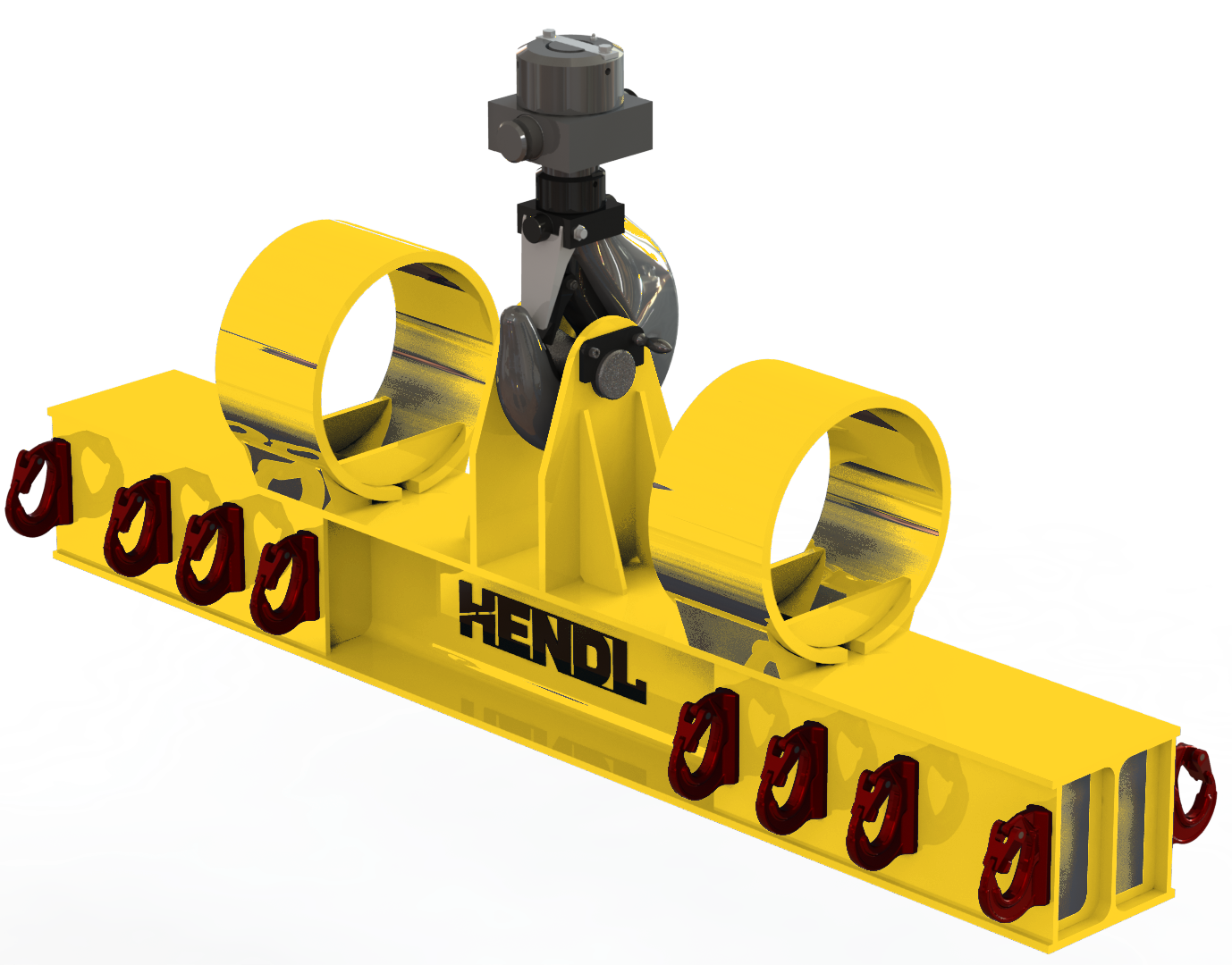
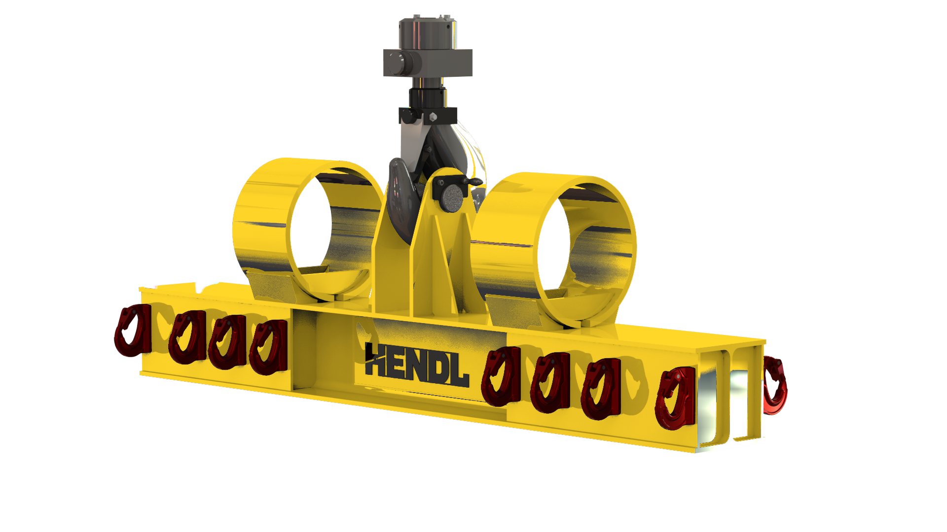
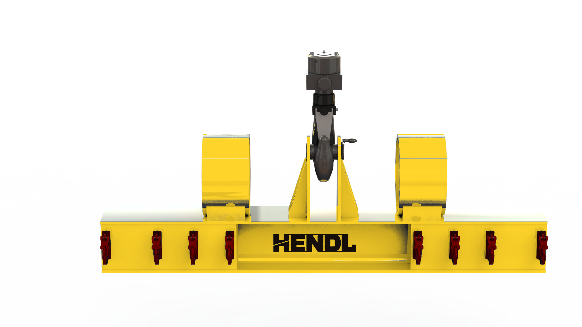
Product introduction
The HENDL Hook-Type Lifting Beam is a family of passive below-the-hook devices engineered to distribute a crane lift across suitable attachment points on large or heavy loads. Separate I-beam and H-frame configurations can feature two, four or multiple lower lifting points for metal products, dies, precast concrete, machinery and specialised industrial loads. The product-family capacity extends up to 200 metric tonnes; higher loads are subject to project-specific engineering.
Standard Capacity And Dimensions
Up to 200 t is the upper capacity class of the P017 product family, not the proven rating of the pictured unit or a universal working load limit for every hook spacing. The permitted load for an individual beam depends on the beam span, pick-up locations, force distribution and suspension arrangements. Fixed or stepped hook positions must be used only within the limits established for the actual model. Sling direction and permissible sling angles have not been established as universal P017 specifications; the approved lifting arrangement and operating instructions define them for each project. Dimensions, hook spacing and available headroom are project-specific.
Working Principle
The beam is suspended from the crane through one of several purpose-designed top arrangements: a central lifting eye, two-leg suspension or a connection for twin crane hooks. Fixed or specially forged lower hooks engage suitable load lifting eyes or the specified rigging arrangement. Fixed-spacing, stepped-position and multi-point hook layouts are offered as distinct designs. P017 operates without a motor, powered hook movement or powered span adjustment; the crane provides the lifting motion. Individual pick-point forces, attachment geometry and any sling angles must be evaluated for the application.
Selection
Engineering inputs include load mass and geometry, centre of gravity, quantity and coordinates of the load lifting points, crane hook type and number, available headroom and environment. The I-beam or H-frame arrangement, hook quantity and pick-point layout are chosen to suit symmetric or asymmetric force distribution. Having several hooks does not mean the load is shared equally: each connection force and the matching rigging specification must be assessed.
Safety and engineered configuration options
Depending on the individual design, measures may include mechanically secured hooks and pins, lower safety-latch hooks, unit-specific WLL identification, lifting-point load distribution and capacity data, sling-angle restrictions, replaceable pins and bushings, inspection/test documentation, parking feet and instructions for trial lifts. Engineered alternatives include two-, four- or multi-hook layouts; swivel hooks or hooks for sling eyes; interchangeable hook/shackle assemblies; single- or twin-crane-hook top rigging; low-headroom structures; I-beam or H-frame construction; provisions for off-centre loads; chain, textile sling or wire-rope interfaces; load-specific adaptors; hot-environment and outdoor arrangements; and compact shipping or storage configurations. Suitability of hooks and rigging is assessed for each load. None of these options should be assumed standard across all models.
Technical Figures For A Quote
To request a quotation, provide the payload description and drawing, maximum load mass, centre-of-gravity position, number and coordinates of lifting eyes, required hook spacing, crane hook count and type, available lifting headroom, proposed slings and hook connections, duty cycle and site conditions. For asymmetric loads, a lifting plan or estimated loads per pick-up point is particularly helpful. Include any high-temperature, outdoor or storage requirements.
Questions
What is a hook-type lifting beam used for?
It distributes the lifting force from a crane across two, four or more suitable attachment points on the payload. The device can be engineered for large dies, fabricated steelwork, precast elements and machinery requiring multiple lifting points. P017 is passive: the lifting movement is provided by the crane.
Does every hook lifting beam have a 200 t capacity?
No. Up to 200 t describes the upper class of the product family. The working load limit of a particular beam depends on its span, hook count, loads at individual pick-up points, top rigging, lower connections and operating conditions. A photograph does not establish the rated capacity of the illustrated unit.
How are hook positions and sling angles determined?
Fixed, stepped or multi-point hook layouts are designed for the application. Sling direction, the locations of load lifting eyes and the suspension geometry affect the forces in each connection. Therefore, no single hook spacing or permissible sling angle is advertised for every P017 unit; those limits are defined by the project calculations and the operating instructions for the actual model.
Related Equipment
Quote