
Products · Lifting And Spreader Beams
LIFTING BEAMS & SPREADERS
Motorized Rotating Lifting Beam
Controlled 360° Orientation for Heavy Loads
Orient crane-suspended industrial loads about the vertical axis using a slewing bearing, gearbox and inverter-controlled motor.
- Up to 100 t
- Product-family capacity
- 0–360°
- Vertical-axis positioning
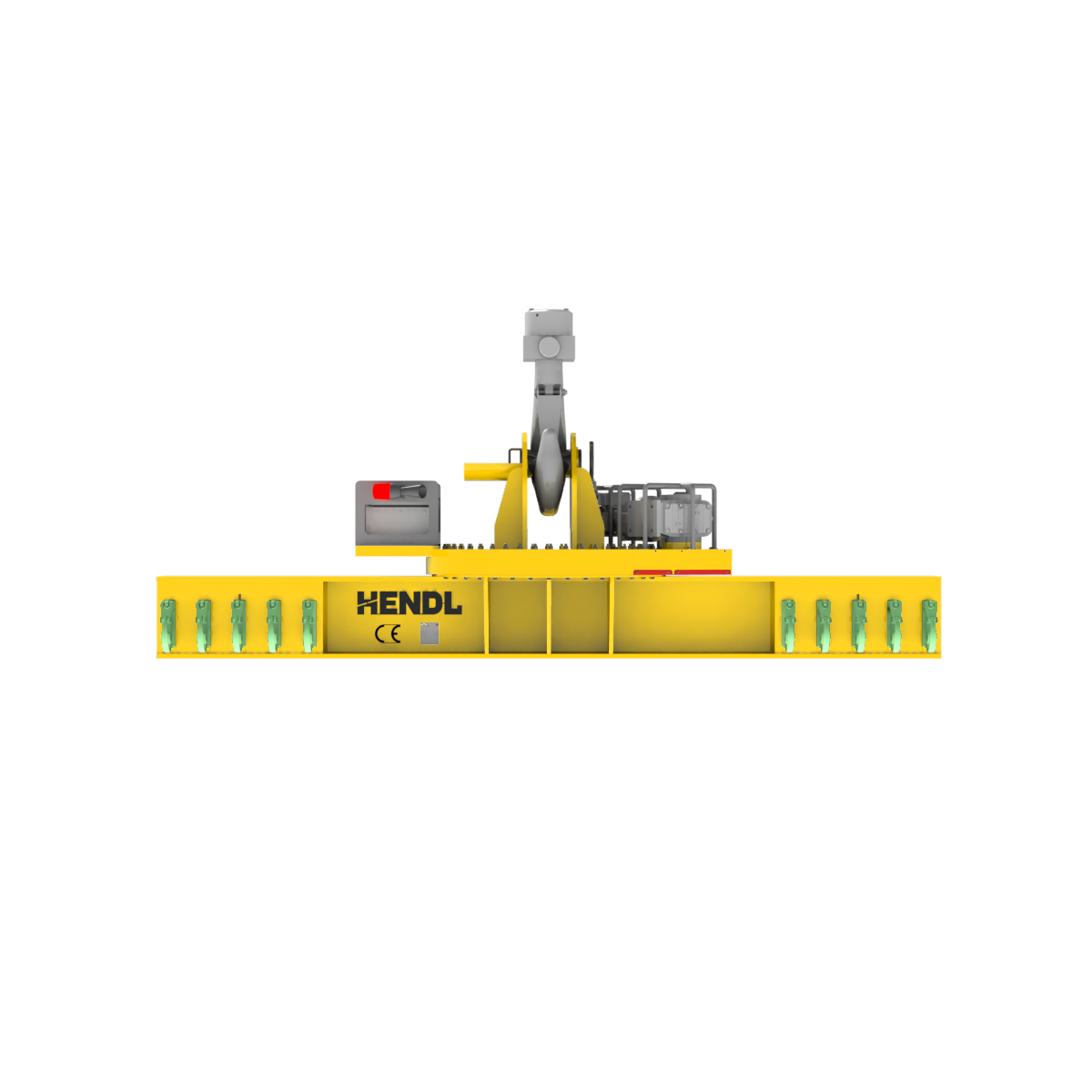
Loading frame
Product introduction
The HENDL Motorized Rotating Lifting Beam is a family of powered below-the-hook devices designed to orient suspended heavy loads about a vertical axis. Separate structural, suspension and lower lifting configurations can be engineered for metal products, dies, machinery, precast concrete and other industrial loads. The product-family capacity extends up to 100 metric tonnes; higher ratings require dedicated engineering. Powered orientation does not mean turning the load upside down about a horizontal axis.
Standard Capacity And Dimensions
Up to 100 t is the upper capacity class of the product family, not the established WLL of the illustrated unit or a rating applicable to every beam span. The 0–360° figure denotes a vertical-axis angular positioning range, not unrestricted repetitive rotation, universal rotary power transfer or one fixed speed for all models. Inverter-adjustable rotation speed, beam dimensions, lifting-point spacing and suspension geometry are project-specific. Powered rotation of suspended loads is permitted only within the actual unit’s rated load, rigging and safeguarding limits. Listed safety features and accessories are configuration-dependent.
Working Principle
A slewing bearing and pinion-and-gear drive are incorporated between the upper crane suspension and the load-carrying beam. An electric motor, gearbox and variable-frequency drive provide controlled vertical-axis orientation while the load is suspended, within the operating limits of the specific design. The specified 0–360° angular positioning range is not a claim of unlimited continuous revolutions. Power routing, travel limits, braking and position retention are engineered to suit each configuration. Manual or powered adjustment of lower lifting-point spacing is a separate engineered option, not the primary powered function.
Selection
Engineering inputs include the payload mass, dimensions and centre of gravity; lifting-eye coordinates; required orientation angle; swept area and site clearances; crane hook type and number; and available power. Suspension from a single crane hook, twin crane hooks or two-leg chain/sling rigging is possible through different engineered configurations. Lower arrangements with two, four or multiple lifting points require analysis of individual pick-point forces and connection suitability. Rotation speed and controls are selected for the application and duty cycle.
Safety, controls and engineered options
Depending on the engineered model, safeguards can include emergency stopping, controlled motor braking and position retention; measures against uncontrolled motion following power loss; mechanical slew stops; angular limits and encoders or position sensors; motor-current/torque protection; secure load attachments; coordinated movement for twin-hook cranes; swept-area operating restrictions; and visual/audible warnings. Unit-specific WLL identification, engineering calculations and test/operating documents apply to the actual machine. Available engineered configurations may include single- or twin-crane-hook or two-leg suspension; two, four or multiple lower points; interchangeable hooks and shackles; manual or powered lower spacing adjustment; off-centre load balancing; battery supply; crane control or PLC integration; wireless controls with wired backup; compact or severe-duty versions; and maintenance and parking provisions. Lower-point adjustment under load requires a purpose-designed, separately assessed configuration.
Technical Figures For A Quote
For a quotation, share the payload drawing, mass, overall dimensions and centre-of-gravity location; number and coordinates of lifting points; single- or twin-hook crane arrangement; available headroom; required orientation range and operating frequency. Specify whether crane-fed power or a battery solution is preferred, along with control/automation needs, site clearances, operating temperature and indoor/outdoor conditions. If optional lower-point spacing adjustment is required, state whether any movement under load is envisaged.
Questions
What does a motorized rotating lifting beam do?
It allows a crane-suspended load to be oriented about the vertical axis under controlled power. This helps align long or specially shaped industrial loads with the required installation or handling position. The beam provides plan-view orientation; it does not invert the payload about a horizontal axis.
Does every unit handle 100 t and rotate continuously?
No. Up to 100 t is a product-family upper capacity, while an individual beam is rated according to its span, lifting-point geometry and rigging. The 0–360° positioning range does not imply indefinite continuous revolutions. Actual speed, angular travel and cable management are defined for each design.
Can the load be rotated while suspended, and how is it powered?
Yes, where the actual model is designed for suspended-load orientation and its rated-load, rigging and safety requirements are met. Power can be supplied from the crane or, in a separate configuration, from an onboard battery. Suspension and controls are tailored to the crane; adjustment of lower hook spacing is a distinct optional function.
Related Equipment
Quote