
RAIL TRANSFER & UPENDING SYSTEMS
Rail-Guided Coil Transfer & Upending System
Powered Coil Transfer and 90° Upending in One Machine
Integrated rail-mounted system for steel, aluminium and slit-coil packs, with controlled 90° upending after the carriage has stopped.
- Up to 50 t
- Load capacity
- 90°
- Two-way upending
Product introduction
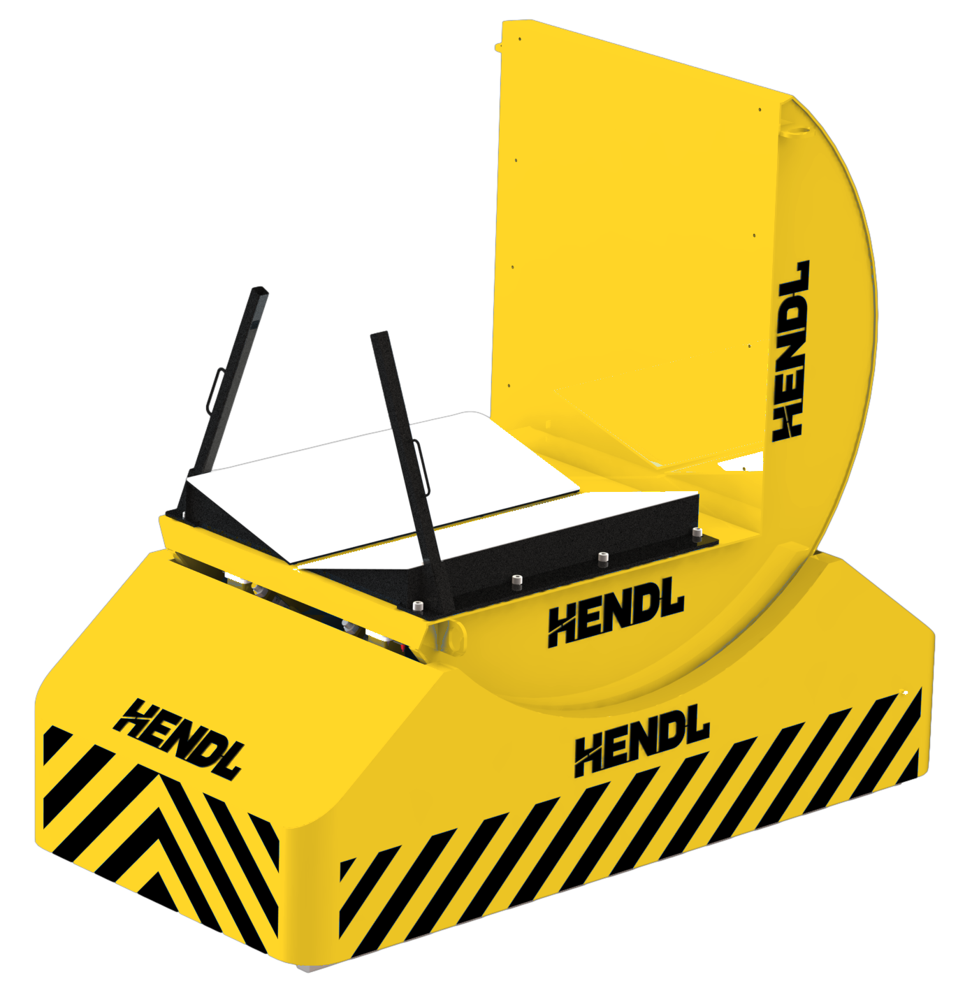
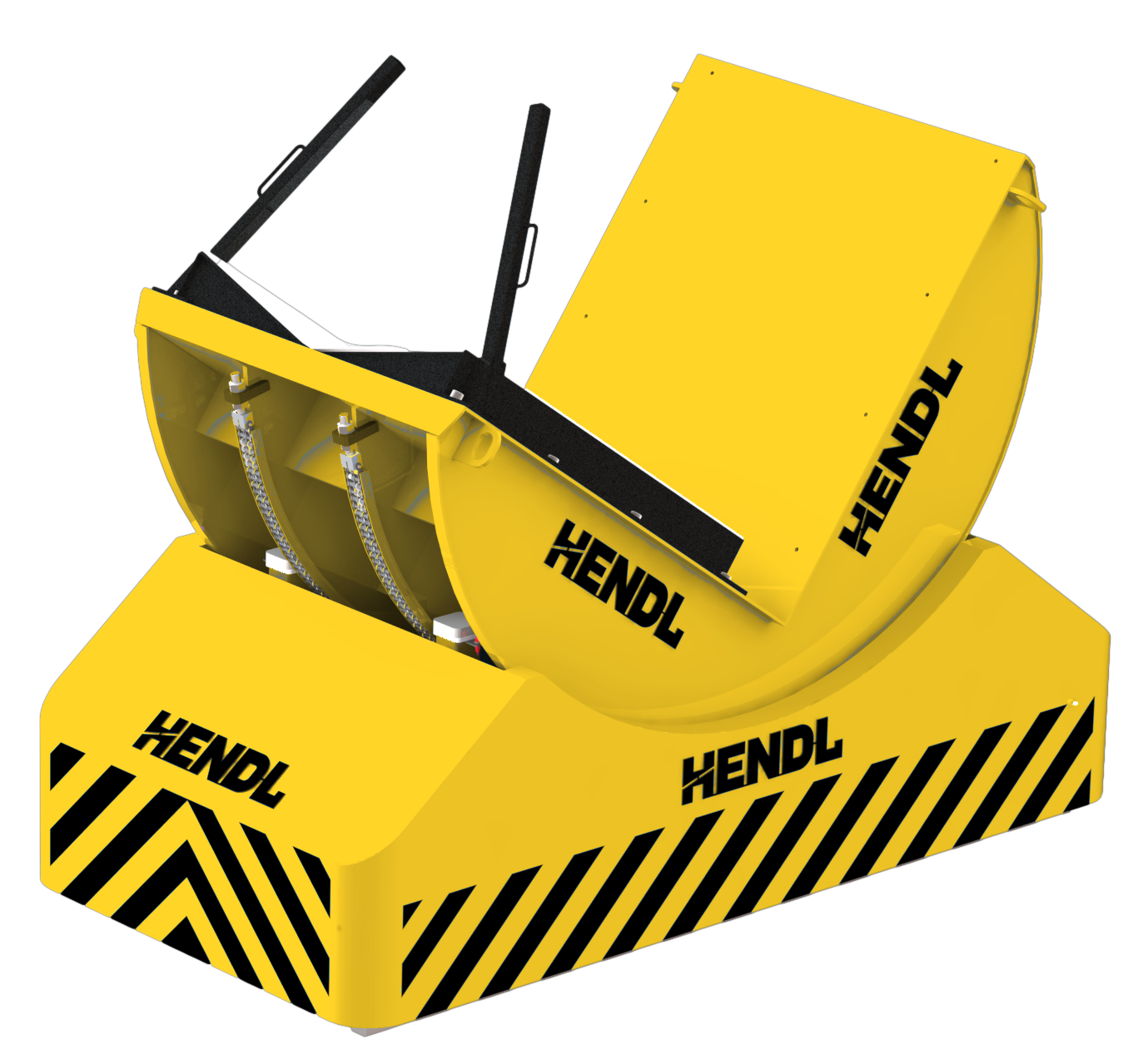
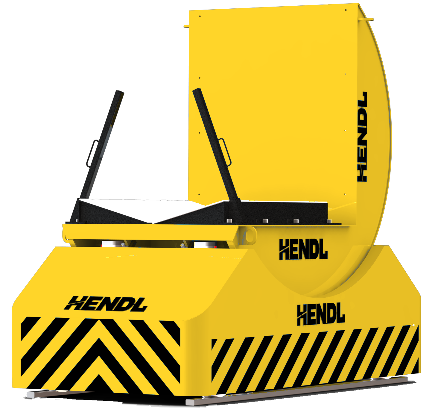
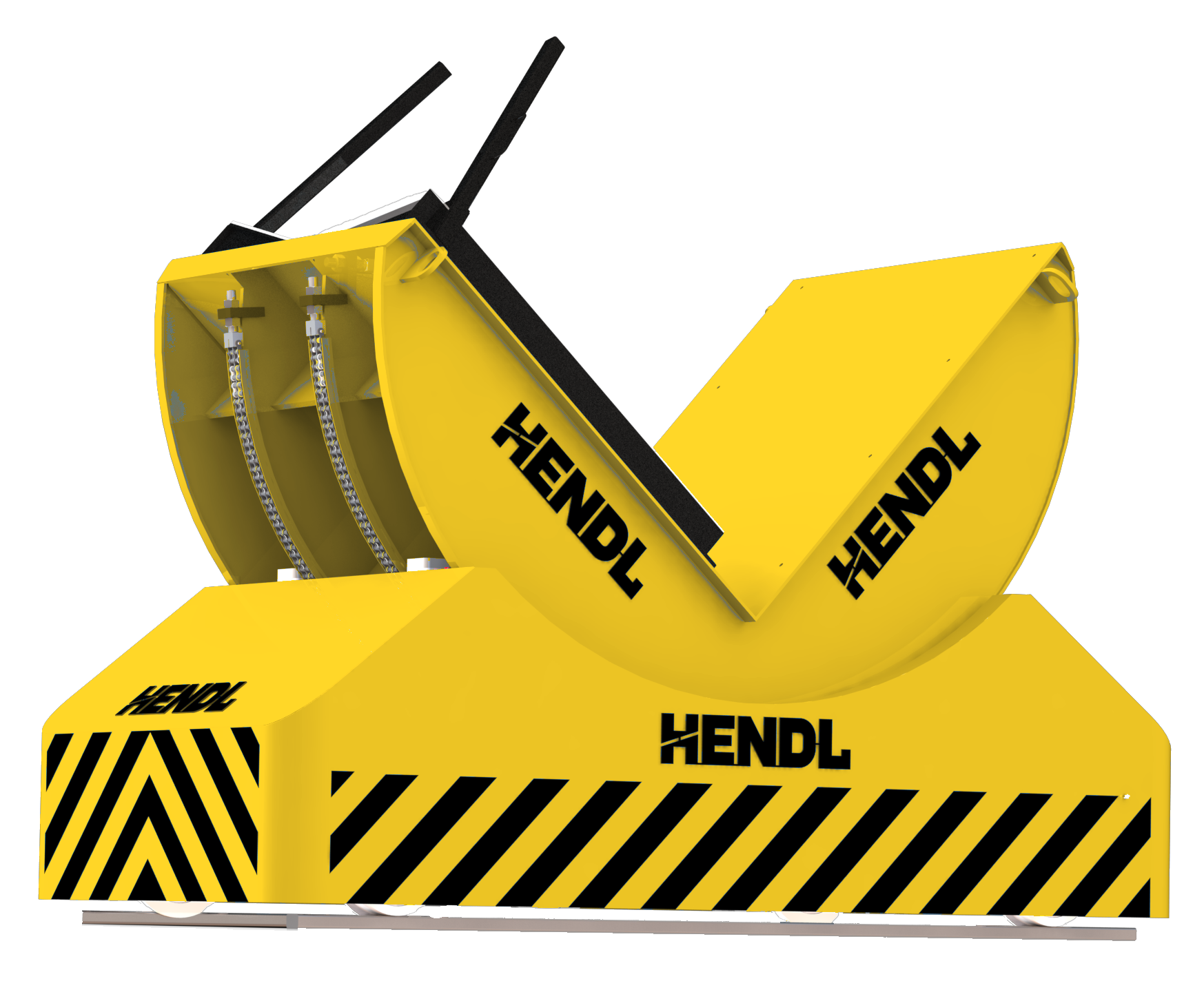
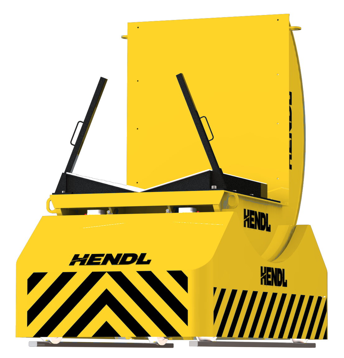
The HENDL Rail-Guided Coil Transfer & Upending System combines powered in-plant transport with a 90° coil-orientation change in a single engineered machine. It is designed for steel and aluminium coils and slit-coil packs moving between production stations. The product family is available for loads up to 50 metric tonnes, with each machine sized to its rail route, coil geometry and operating conditions.
Standard Capacity And Dimensions
The published product-family capacity is up to 50 t; higher capacities require a bespoke engineering assessment.
Travel speed can be designed within an application-dependent range of 0–10 km/h.
The upper speed is neither suitable nor guaranteed for every load, route or workplace; permissible speed must account for the actual mass, track layout, braking distance, obstacle detection and site risk assessment.
Coil and rail dimensions, upending time, lifting stroke and drive power are project-specific.
No universal 50 t / 10 km/h operating combination is implied.
Working Principle
The coil is supported in a V-shaped cradle and retained by mechanical stops. A powered carriage moves it along the designated rail track to the target station. Only after the carriage has stopped completely and the required position has been confirmed does a separate electric motor and gearbox drive the upending mechanism through 90°, changing the coil axis from horizontal to vertical or back. Travel and upending are controlled sequential operations, not simultaneous movements under load. The C-shaped upending structure and the load-supporting V-cradle describe different functional parts of the same integrated unit.
Selection
Engineering inputs include coil weight, outside diameter and width, bore, centre of gravity, winding or packaging arrangement, rail gauge, travel distance, floor conditions, station locations and required duty. Cable-management systems, conductor-bar supply and battery power are separate configurations. Wired pendant, wireless remote or automated station control can be selected. Vertical lifting, mandrel alignment, automatic centring and precise positioning are additional project-dependent options.
Safety and custom engineering options
Depending on the project, provisions can include rail end limits and buffers, travel motor braking, obstacle detection or laser scanning, upending end stops, position-based permission to upend, positive load retainers, emergency stop and access safeguarding, audible/visual warnings, load or torque protection, power-loss holding arrangements, station sensors and cable or power-line protection. Optional engineering covers conveyor integration, direct coil loading onto machine mandrels, vertical lift, adjustable or interchangeable V-cradles, polyamide or UHMW contact surfaces, automatic coil centring, multi-station sequencing, compact chassis for restricted aisles, customised rail gauge, forklift or C-hook loading clearance and maintenance lockout. Not every feature is standard across all models.
Technical Figures For A Quote
For a technical quotation, provide the coil material (steel, aluminium or slit-coil packs), minimum and maximum weights, outside diameter, coil width, bore diameter, rail gauge, total route length, station count, loading and discharge elevations, required upending direction, target travel speed, daily duty, available power infrastructure and plant layout. Coil drawings and a rail-route plan are helpful.
Questions
Does the unit only transfer coils, or can it also upend them?
Both functions are integrated. The rail-mounted carriage transfers the load to a station, stops and confirms its position. The separately powered upender then rotates the supported coil by 90° between horizontal-axis and vertical-axis orientations. Travel and upending do not run simultaneously.
Can a 50 t coil always travel at 10 km/h?
No. Up to 50 t is the published family capacity, while 0–10 km/h is an application-dependent travel-speed design range. The permissible combination is established from the actual load, track layout, braking performance, obstacle protection and plant risk assessment.
Are the track dimensions and power supply standardised?
Track gauge and length, coil dimensions and upending time are determined for each project. Cable supply, conductor bar and battery-powered versions are separate configurations; vertical lifting, machine-mandrel alignment and automated station positioning can be engineered as options.
Related Equipment
Quote