Products · Crane Power Supply Systems

Cranes and power supply

Fully Enclosed Conductor Rail Systems

Mobilis Elite, INNO, Current Collector Trolleys and System Accessories

Fully enclosed conductor rail systems provide electrical power to cranes and moving industrial equipment along a fixed path.

Within the Mobilis Elite and INNO product ranges, HENDL offers supply options for conductor rail profiles, current collector trolleys, feed components, connecting parts and mounting accessories.

System selection is based on required current, line length, travel distance and installation conditions.

How Does It Work?

Conductor rail profiles are mounted in fixed positions along the power supply route. The current collector trolley on the moving equipment makes electrical contact with the conductors inside the rail to transmit power to the equipment.

The rated current of the conductor rail and the rated current of the collector trolley are different technical specifications. Both components must be considered together when selecting a suitable system.
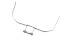
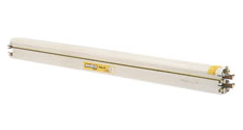
This model shows the product's shape. It is not a dimensioned drawing.

Mobilis Elite fully enclosed conductor rail line

Mobilis Elite

Mobilis Elite is a multipole, fully enclosed conductor rail system with component and accessory options suitable for different travel paths.

In addition to straight-line applications, component options are available for curved routes and special line layouts.

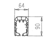
Cross-section of the INNO fully enclosed conductor rail profile

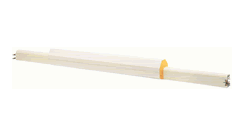
INNO

INNO is a multipole, fully enclosed conductor rail system intended for straight-line applications.
It is assessed together with rail profiles, connection parts, hangers and current collector components.
INNO's technical specifications must be presented separately from those of Mobilis Elite.
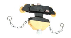
40 A single Elite current collector trolley

Current Collector Trolleys

Current collector trolleys provide an electrical connection between moving equipment and the fixed conductor rail line.

The trolley arrangement is selected according to the required current and conductor rail type. Compatibility of contact elements and mechanical connections with the relevant product must be checked.

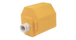
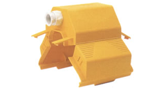
Elite end-feed box

Power Feed and Connection Components

Feed boxes, rail joint elements, end caps and expansion components are system parts used to install a conductor rail line.

Component selection depends on the rail model, line layout and mounting requirements.

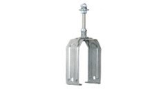
Elite sliding hanger

Hangers and Support Components

Hangers and support brackets are used to attach the conductor rail line to the supporting structure.

The mounting arrangement must be determined according to the line geometry and the relevant manufacturer's installation requirements.

Mobilis Elite Features

Cross-section of the Mobilis Elite fully enclosed conductor rail profile
  • Rated currents: 20, 40, 60, 100, 130, 160 and 200 A.
  • Quick assembly: connection screws and protective lips are pre-installed. Accessories clip into place. Connections use break-off-head screws.
  • Protection: completed line IP23, EN 60529. The profile is made of self-extinguishing PVC.
  • The profile is light and rigid. Expansion joints are considered separately for long lines. The system is modular.
  • Carbon brushes are removable. Connections can be disassembled.
  • Maximum voltage for the rail element: 750 V. Standard lengths are 4, 3, 2 and 1 m.

Elite Parts and Accessories

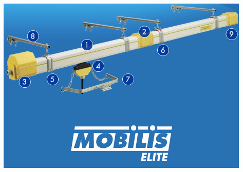
Numbers are markers in the overview image. Conflicting part codes have been left as shown in the table.

Numbered Elite line layout. The image bears the Mobilis Elite marking.
  1. Rail element
  2. Joint cover
  3. End feed
  4. Current collector trolley
  5. Sliding hanger
  6. Fixed hanger
  7. Carrier
  8. Mounting bracket
  9. End cap

Rail element

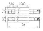
Elite rail elementDimensioned drawing of an Elite rail element, 64 mm and 90 mm

Rail element

Self-extinguishing PVC profile. Standard lengths of 4, 3, 2 and 1 m. Special lengths on request. Maximum voltage 750 V. Cross-section drawing 64 × 90 mm.

The 20 A impedance unit is printed as ohm/n. The other units in the same row are ohm/m.

In the 4 m row, the 160 A 5-pole and 200 A 4-pole entries have the same code: ME8284-TR. The 200 A 5-pole cell is printed as MR8285-TR. The 2 m 130 A 5-pole code, ME5133, is identical to the 3 m code. These four cells have not been corrected.

Code table
20, 40, 60 and 100 A. The 20 A material designation remains steel.
Entry20 A, 4 poles20 A, 5 poles40 A, 4 poles40 A, 5 poles60 A, 4 poles60 A, 5 poles100 A, 4 poles100 A, 5 poles
Phase cross-section16 mm², steelCopper 10 mm²Copper 16 mm²Copper 24 mm²
Earth cross-section16 mm², steelCopper 10 mm²Copper 16 mm²Copper 24 mm²
Impedance, 50 Hz, 35 °C0,0121 ohm/n0,00178 ohm/m0,00126 ohm/m0,00081 ohm/m
Weight, kg/m1,71,81,51,61,81,92,02,1
4 mME4204ME5204ME4404ME5404ME4604ME5604ME4104ME5104
3 mME4203ME5203ME4403ME5403ME4603ME5603ME4103ME5103
2 mME4202ME5202ME4402ME5402ME4602ME5602ME4102ME5102
1 mME4201ME5201ME4401ME5401ME4601ME5601ME4101ME5101
Special lengthME4200ME5200ME4400ME5400ME4600ME5600ME4100ME5100
Expansion jointME8020ME8520ME8040ME8540ME8060ME8560ME8100ME8510
130, 160 and 200 A. Conflicting codes have been left as shown in the table.
Entry130 A, 4 poles130 A, 5 poles160 A, 4 poles160 A, 5 poles200 A TR, 4 poles200 A TR, 5 poles
Phase cross-sectionCopper 35 mm²Copper 48 mm²Copper 70 mm²
Earth cross-sectionCopper 35 mm²Copper 24 mm²Copper 35 mm²
Impedance, 50 Hz, 35 °C0,00059 ohm/m0,00043 ohm/m0,00032 ohm/m
Weight, kg/m2,42,72,63,03,33,9
4 mME4134ME5134ME4164ME8284-TRME8284-TRMR8285-TR
3 mME4133ME5133ME4163ME5163ME8283-TRME8289-TR
2 mME4132ME5133ME4162ME5162ME8282-TRME8286-TR
1 mME4131ME5131ME4161ME5161ME8281-TRME8287-TR
Special lengthME4130ME5130ME4160ME5160ME8280-TRME8288-TR
Expansion jointME8013ME8513ME8016ME8516ME8290-TRME8291-TR

Expansion joint, joint cover and end cap

Elite expansion jointDimensioned drawing of the Elite expansion joint

Expansion joint

The joint is installed at the centre of the line. The threshold is 140 m for 20 A, 150 m for 40–100 A and 250 m for 130–200 A. An expansion joint is used if the line exceeds this threshold. Joint codes are in the rail element table.

Elite joint coverDimensioned drawing of the Elite joint cover

Joint cover

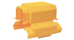
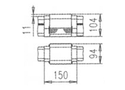
Covers the joint between two rail elements. IP23. 0,2 kg. ME1000.

Elite end capDimensioned drawing of the Elite end cap

End cap

IP23. Area inaccessible to the trolley: 35 mm. 0,3 kg. ME1400.

Elite limit pinDimensioned drawing of the Elite limit pin

Limit pin

Zinc-plated steel rod. Length 400 mm, diameter 10 mm. 0,570 kg. ME1550.

Feed boxes

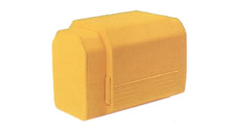
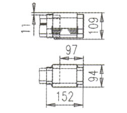
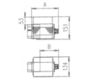
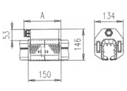
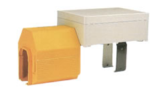
Elite end-feed boxDimensioned drawing of the Elite end-feed box

End feed

20, 40, 60 and 100 A. IP23. 0,4 kg. Area inaccessible to the trolley: 35 mm.

Code table
End-feed dimensions and code.
OutletA, mmB, mmCodeCable diameter
M25181126ME120013–19 mm
M32183128ME123015–25 mm
M40186132ME125021–32 mm
Elite in-line feed box M25 and M32Dimensioned drawing of the Elite in-line feed M25 and M32

In-line feed M25 and M32

20–100 A. IP23. 0,3 kg.

Code table
In-line feed M25 and M32.
OutletA, mmCodeCable diameter
M25169ME130013–19 mm
M32170ME133015–25 mm
Elite in-line feed box M40Dimensioned drawing of the Elite in-line feed M40

In-line feed M40

20–100 A. IP23. Cable 21–32 mm. 1,5 kg. 4 poles ME1332, 5 poles ME1329.

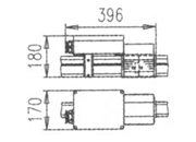
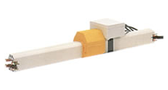
130 A and 200 A Elite feed boxDimensioned drawing of the 130 A and 200 A feed box

130 A and 200 A

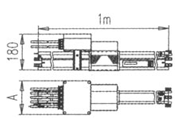
Supplied mounted on a 1 m rail element. IP23. Weight including 2 m connection cable: 15 kg for 130 A and 24 kg for 200 A. Two hangers are used. Dimension A is 220 mm.

Code table
130 A and 200 A feed code. The 4 m, 5-pole cell is empty.
Rated currentCross-sectionCable diameterLength4 poles5 poles
130 A35 mm²16 mm1 mME1313ME1317
130 A35 mm²16 mm4 mME1343No code
200 A70 mm²20,5 mm1 mME8299ME8294
200 A70 mm²20,5 mm4 mME8279No code

Current collector trolleys

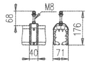
40 A single Elite current collector trolleyDimensioned drawing of the 40 A single trolley

Single, 40 A

Box outlet ME3043 and ME3051. Cable outlet ME2043 and ME2051. 0,6 kg.

80 A double Elite current collector trolleyDimensioned drawing of the 80 A double trolley

Double, 80 A

Box outlet ME4042 and ME4050. Cable outlet ME4047-1M and ME4051. 1,1 kg.

120 A triple Elite current collector trolleyDimensioned drawing of the 120 A triple trolley

Triple, 120 A

Box outlet ME5040 and ME5050. Cable outlet ME5049-1M and ME5059-1M. 1,6 kg.

Hangers, carriers and brackets

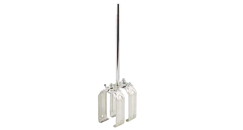
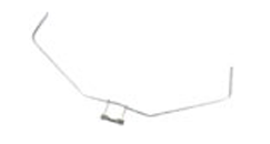
Elite sliding hangerDimensioned drawing of the Elite sliding hanger

Sliding hanger

ME1510. 0,1 kg. 2 units per 4 m element for 20–130 A lines. 3 units for 200 A lines.

Elite fixed hangerDimensioned drawing of the Elite fixed hanger

Fixed hanger

ME1500. 0,1 kg. Supplied with four anchor screws.

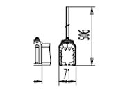
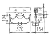
Single Elite trolley carrierDimensioned drawing of the single carrier

Single carrier

ME1600. 0,6 kg. Square bar 20–50 mm. Horizontal clearance ±50 mm.

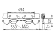
Double Elite trolley carrierDimensioned drawing of the double carrier

Double carrier

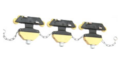
ME1610. 1,1 kg.

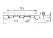
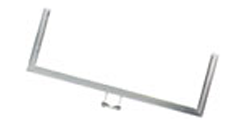
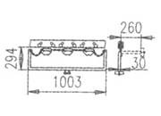
Triple Elite trolley carrierDimensioned drawing of the triple carrier

Triple carrier

ME1630. 2,6 kg.

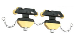
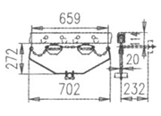
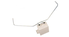
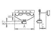
Elite trolley carrier with boxDimensioned drawing of the carrier with box

Carrier with box

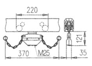
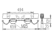
Cable diameter 22–30 mm. Single cable up to 5×16 mm², double up to 5×16 mm², triple up to 5×25 mm².

Code table
Carrier with box. A, B and C refer to the dimensions in the drawing.
Type4 poles5 polesFM 35 °CABCWeight
SingleME1660ME1660%1003701941541,4 kg
DoubleME1640ME1645%617022722321,9 kg
TripleME1650ME1655%4010032942603,4 kg
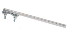
Elite mounting bracketDimensioned drawing of the Elite mounting bracket

Mounting bracket

ME1760 and ME1780 are listed for the 200 A line. The dimension table also shows ME1750 in both the 600 mm and 850 mm rows. The ME1700 cross-section is 10 × 20 mm.

Code table
Mounting bracket.
CodeLengthCross-sectionWeight
ME1700380 mm10 × 20 mm0,5 kg
ME1750500 mm15 × 20 mm0,6 kg
ME1750600 mm30 × 30 mm1,0 kg
ME1750850 mm30 × 30 mm1,2 kg
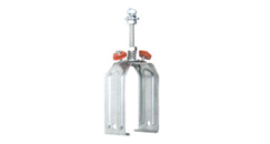
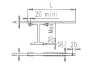
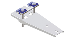
Elite clamp-on bracket

Clamp-on bracket

Quick-mounting bracket ME1799.

Quotation

Tell Us About Your Project