
Products · Lifting And Spreader Beams
LIFTING BEAMS & SPREADERS
Motorized Rotating Paper Roll Lifting Beam
Lift the Tambour. Control Its Orientation.
Project-engineered journal support and continuous 360° motorized orientation about the vertical axis.
- Engineered to order
- Rated lifting capacity
- Project-specific
- Hook spacing and layout
Frame loading
Product introduction
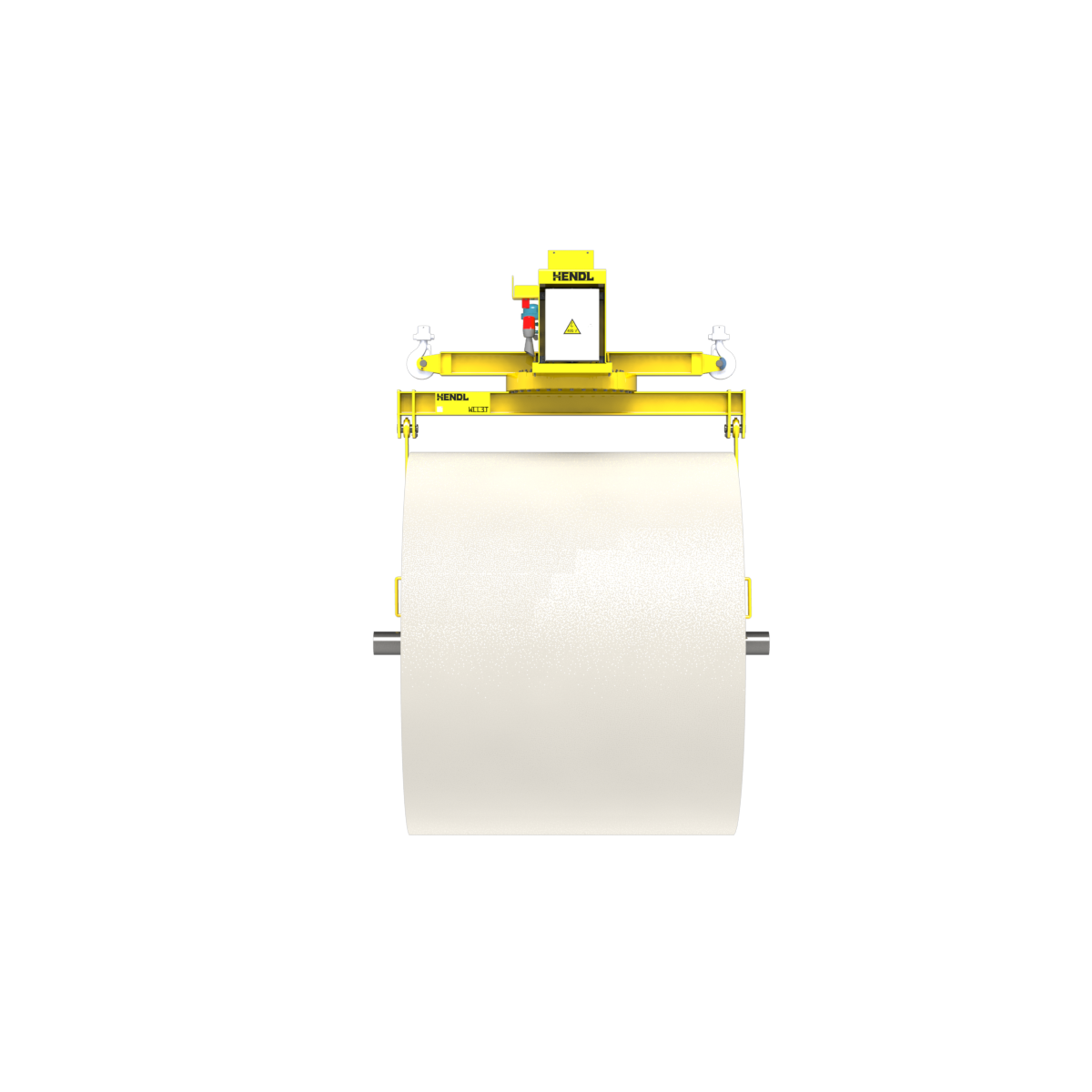
The HENDL Motorized Rotating Paper Roll Lifting Beam is engineered to lift, transfer and orient paper tambours fitted with supporting shafts or journals at both ends. Long-hook arms support the load at suitable shaft ends, while a motor-driven slewing assembly enables controlled orientation about the vertical axis. Each configuration is developed for the drum geometry, crane arrangement and duty conditions of the paper mill or production line.
Standard Capacity And Dimensions
Different capacities and dimensions can be engineered. Numeric capacity ranges, rotation speed, self-weight, dimensional limits and power requirements will be published only after model-level verification. Capacity markings visible on a visualization must not be treated as a rating for the complete product range.
Working Principle
The tambour is engaged at its designated end journals by two long-hook arms. The crane suspension is configured around the verified centre of gravity and lifting arrangement. Shaft support, hook seating and load balance are assessed during engineering. The motorized slewing system is intended to provide continuous 360° orientation of the suspended load about the vertical axis. Safe power and control continuity must be engineered for continuous rotation; uncontrolled cable twisting is not acceptable.
Selection
Capacity and beam geometry are application-specific rather than restricted to one fixed size. Engineering inputs include total tambour mass, width and outside diameter, shaft-end diameter and overhang, journal shoulder details, required hook spacing, centre of gravity, available crane headroom and duty cycle. Single- or dual-hook crane suspension is selected for the project. The hook spacing is designed to suit the specified load; powered or manual telescopic adjustment is not represented as a standard feature.
Configuration and control options
Crane-side suspension for one or two hooks; motor-driven slewing with suitable speed control; optional radio remote control; optional standalone control cabinet; and project-dependent additional hook-retention, position/limit, overload and tilt-monitoring arrangements. Final features and safety architecture remain subject to engineering validation.
Technical Figures For A Quote
For a quotation, provide the total drum mass, width and outside diameter, dimensioned drawings of both end journals, distance between shaft ends, crane-hook quantity and hook geometry, available headroom, electrical supply, working environment and intended operating cycle. Layout drawings or drum photographs are helpful.
Request an Engineered Quotation
Questions
Which paper rolls can this lifting beam handle?
It is designed for paper tambours with suitable support shafts or journals at both ends. Journal geometry, load and hook contact are verified per project. It is not intended to clamp the outer paper surface.
Can the suspended load rotate through 360 degrees?
Yes. The approved concept provides continuous motorized 360° orientation around the vertical axis. The required power transfer, cable management, controls and protective functions are specified for each application.
Can it be configured for single- and double-hook cranes?
Yes. Both suspension concepts may be engineered. Hook spacing, load centre of gravity and crane conditions determine the final arrangement.
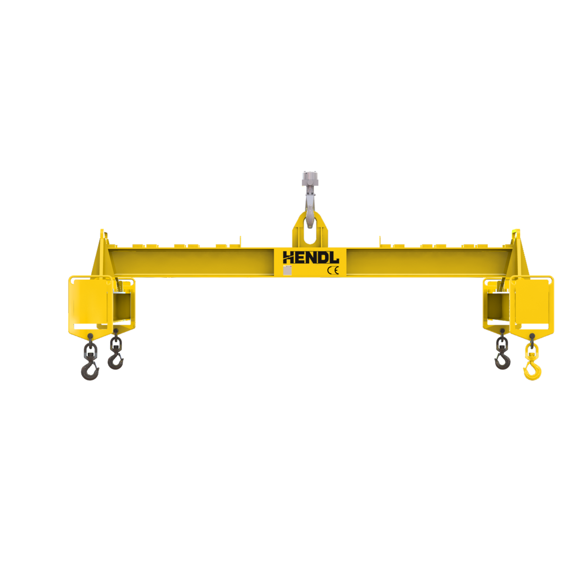 Adjustable Lifting Beam
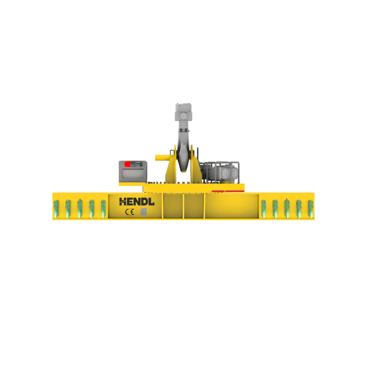 Motorized Lifting Beam
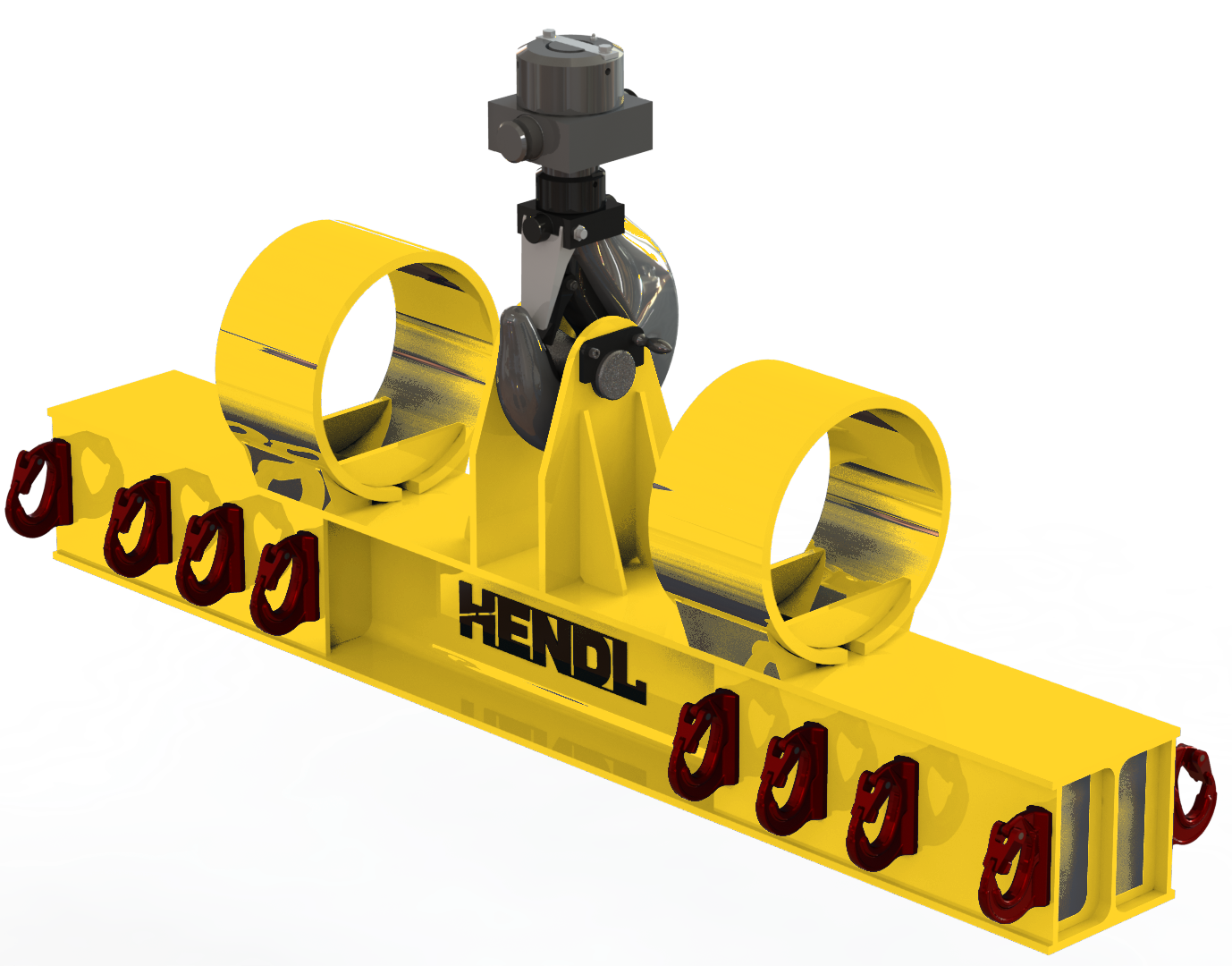 Hook Lifting Beam
Quote